STM32F407系統時鐘配置
時鐘樹
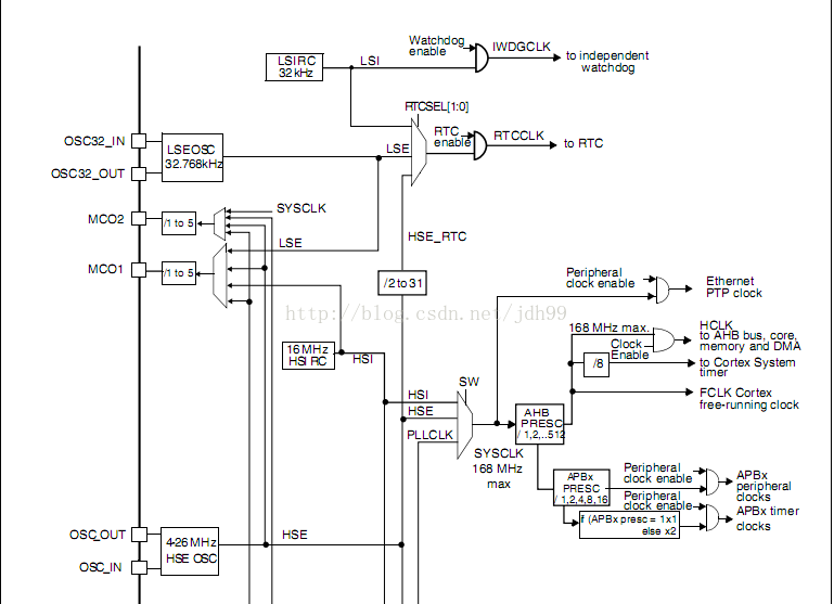
方法一,采用官方庫提供的配置(這里外部晶振25MHz,系統配置為168MHz)
STM32F4啟動與STM32F10X不同,時鐘已經默認配置好
啟動代碼,文件:startup_stm32f4xx.s
Reset handler
Reset_Handler PROC
EXPORT Reset_Handler [WEAK]
IMPORT SystemInit
IMPORT __main
LDR R0, =SystemInit
BLX R0
LDR R0, =__main
BX R0
ENDP
可以看出,在進入main函數之前,系統調用了SystemInit函數.
SystemInit函數分析:SystemInit函數位于system_stm32f4xx.c文件中.此文件提供幾個宏定義可以設置各個時鐘:
/************************* PLL Parameters *************************************/
/* PLL_VCO = (HSE_VALUE or HSI_VALUE / PLL_M) * PLL_N */
#define PLL_M 25
#define PLL_N 336
/* SYSCLK = PLL_VCO / PLL_P */
#define PLL_P 2
/* USB OTG FS, SDIO and RNG Clock = PLL_VCO / PLLQ */
#define PLL_Q 7
/******************************************************************************/
而晶振頻率則是在文件stm32f4xx.h中進行設置:
外部晶振:
#if !defined (HSE_VALUE)
#define HSE_VALUE ((uint32_t)25000000) /*!< Value of the External oscillator in Hz */
#endif /* HSE_VALUE */
內部晶振:
#if !defined (HSI_VALUE)
#define HSI_VALUE ((uint32_t)16000000) /*!< Value of the Internal oscillator in Hz*/
#endif /* HSI_VALUE */
綜上,可以得出默認配置中:
鎖相環壓腔振蕩器時鐘PLL_VCO = 25 / 25 * 336 = 336MHz
系統時鐘SYSCLK = 336 / 2 = 168MHz
USB,SD卡時鐘 = 336 / 7 = 48MHz
SystemInit函數代碼:
/**
* @brief Setup the microcontroller system
* Initialize the Embedded Flash Interface, the PLL and update the
* SystemFrequency variable.
* @param None
* @retval None
*/
void SystemInit(void)
{
/* FPU settings ------------------------------------------------------------*/
#if (__FPU_PRESENT == 1) && (__FPU_USED == 1)
SCB->CPACR |= ((3UL << 10*2)|(3UL << 11*2)); /* set CP10 and CP11 Full Access */
#endif
/* Reset the RCC clock configuration to the default reset state ------------*/
/* Set HSION bit */
RCC->CR |= (uint32_t)0x00000001;
/* Reset CFGR register */
RCC->CFGR = 0x00000000;
/* Reset HSEON, CSSON and PLLON bits */
RCC->CR &= (uint32_t)0xFEF6FFFF;
/* Reset PLLCFGR register */
RCC->PLLCFGR = 0x24003010;
/* Reset HSEBYP bit */
RCC->CR &= (uint32_t)0xFFFBFFFF;
/* Disable all interrupts */
RCC->CIR = 0x00000000;
#ifdef DATA_IN_ExtSRAM
SystemInit_ExtMemCtl();
#endif /* DATA_IN_ExtSRAM */
/* Configure the System clock source, PLL Multiplier and Divider factors,
AHB/APBx prescalers and Flash settings ----------------------------------*/
SetSysClock();
/* Configure the Vector Table location add offset address ------------------*/
#ifdef VECT_TAB_SRAM
SCB->VTOR = SRAM_BASE | VECT_TAB_OFFSET; /* Vector Table Relocation in Internal SRAM */
#else
SCB->VTOR = FLASH_BASE | VECT_TAB_OFFSET; /* Vector Table Relocation in Internal FLASH */
#endif
}
SetSysClock函數分析,在SetSysClock函數中,配置了系統時鐘,PLL倍頻以及分頻系數:
/**
* @brief Configures the System clock source, PLL Multiplier and Divider factors,
* AHB/APBx prescalers and Flash settings
* @Note This function should be called only once the RCC clock configuration
* is reset to the default reset state (done in SystemInit() function).
* @param None
* @retval None
*/
static void SetSysClock(void)
{
/******************************************************************************/
/* PLL (clocked by HSE) used as System clock source */
/******************************************************************************/
__IO uint32_t StartUpCounter = 0, HSEStatus = 0;
/* Enable HSE */
RCC->CR |= ((uint32_t)RCC_CR_HSEON);
/* Wait till HSE is ready and if Time out is reached exit */
do
{
HSEStatus = RCC->CR & RCC_CR_HSERDY;
StartUpCounter++;
} while((HSEStatus == 0) && (StartUpCounter != HSE_STARTUP_TIMEOUT));
if ((RCC->CR & RCC_CR_HSERDY) != RESET)
{
HSEStatus = (uint32_t)0x01;
}
else
{
HSEStatus = (uint32_t)0x00;
}
if (HSEStatus == (uint32_t)0x01)
{
/* Select regulator voltage output Scale 1 mode, System frequency up to 168 MHz */
RCC->APB1ENR |= RCC_APB1ENR_PWREN;
PWR->CR |= PWR_CR_VOS;
/* HCLK = SYSCLK / 1*/
RCC->CFGR |= RCC_CFGR_HPRE_DIV1;
/* PCLK2 = HCLK / 2*/
RCC->CFGR |= RCC_CFGR_PPRE2_DIV2;
/* PCLK1 = HCLK / 4*/
RCC->CFGR |= RCC_CFGR_PPRE1_DIV4;
/* Configure the main PLL */
RCC->PLLCFGR = PLL_M | (PLL_N << 6) | (((PLL_P >> 1) -1) << 16) | (RCC_PLLCFGR_PLLSRC_HSE) | (PLL_Q << 24);
/* Enable the main PLL */
RCC->CR |= RCC_CR_PLLON;
/* Wait till the main PLL is ready */
while((RCC->CR & RCC_CR_PLLRDY) == 0)
{
}
/* Configure Flash prefetch, Instruction cache, Data cache and wait state */
FLASH->ACR = FLASH_ACR_ICEN |FLASH_ACR_DCEN |FLASH_ACR_LATENCY_5WS;
/* Select the main PLL as system clock source */
RCC->CFGR &= (uint32_t)((uint32_t)~(RCC_CFGR_SW));
RCC->CFGR |= RCC_CFGR_SW_PLL;
/* Wait till the main PLL is used as system clock source */
while ((RCC->CFGR & (uint32_t)RCC_CFGR_SWS ) != RCC_CFGR_SWS_PLL);
{
}
}
else
{
/* If HSE fails to startup, the application will have wrong clock configuration. User can add here some code to deal with this error */
}
}
如果外部時鐘啟動失敗,系統會使用內部時鐘
默認配置:
HCLK = SYSCLK / 1 = 168MHz
PCLK2 = HCLK / 2 = 84MHz
PCLK1 = HCLK / 4 = 42MHz
方法二,根據需要重新進行配置(這里外部晶振25MHz,系統配置為168MHz)
自己根據自己外部晶振大小和需要進行配置
void RCC_Config(void)
{
RCC_DeInit(); //RCC寄存器初始化
RCC_HSEConfig(RCC_HSE_ON); //使用外部時鐘
if(RCC_WaitForHseStartUp() == SUCCESS) //等待外部時鐘啟動
{
RCC_PLLCmd(DISABLE); //配置PLL前應先關閉主PLL
RCC_SYSCLKConfig(RCC_SYSCLKSOURCE_PLLCLK); //選擇PLL時鐘為系統時鐘
RCC_HCLKConfig(RCC_SYSCLK_Div1); //HCLK(AHB)時鐘為系統時鐘1分頻
RCC_PCLK1Config(RCC_HCLK_Div4); //PCLK(APB1)時鐘為HCLK時鐘8分頻
RCC_PCLK2Config(RCC_HCLK_Div2); //PCLK(APB2)時鐘為HCLK時鐘2分頻
RCC_PLLConfig(RCC_PLLSource_HSE,25,336,2,7); //PLL時鐘配置,外部晶振為25MHz,系統配置為168MHz
RCC_PLLCmd(ENABLE); //PLL時鐘開啟
while(RCC_GetFlagStatus(RCC_FLAG_PLLRDY) == RESET); //等待PLL時鐘準備好
}
}
上一篇:stm32f407之基本定時器TIM6&TIM7(操作寄存器)
下一篇:CubeMX 時鐘設置 STM32F407VET
推薦閱讀
史海拾趣

設計資源 培訓 開發板 精華推薦
- 【下載】LAT1526 利用SPI的下溢實現回顯功能
- 【下載】LAT1509 STM32G0B1的FDCAN進行通信丟包和多包案例分享
- 【下載】LAT1511 運行Ux_Host_HUB_HID_MSC通過Hub連接U盤讀寫不穩定問題分析
- 【下載】LAT1466 USB x Device HID Standalone的移植
- 【下載】LAT1488 STM32 USBxDevice MSC standalone移植示例
- 【下載】LAT1482 STM32G0單線串口通信幀錯誤問題解析


 FST8045


 京公網安備 11010802033920號