一、中斷配置的步驟
1、使能中斷
2、設置中斷優先級分組
void NVIC_PriorityGroupConfig(uint32_tNVIC_PriorityGroup);
#define NVIC_PriorityGroup_0 ((uint32_t)0x700) /*0位搶占,4位響應 */
#define NVIC_PriorityGroup_1 ((uint32_t)0x600) /*1位搶占,3位響應 */
#define NVIC_PriorityGroup_2 ((uint32_t)0x500) /*2位搶占,2位響應 */
#define NVIC_PriorityGroup_3 ((uint32_t)0x400) /*3位搶占,1位響應 */
#define NVIC_PriorityGroup_4 ((uint32_t)0x300) /*4位搶占,0位響應 */
一般選擇NVIC_PriorityGroup_2,即搶占和響應均有4級。
3、配置NVIC_InitTypeDef結構體
void NVIC_Init(NVIC_InitTypeDef*NVIC_InitStruct);
typedef struct
{
uint8_t NVIC_IRQChannel; /*指定要使能或要失能的IRQ通道,這個值可以從stm32f10x.h中引用*/
uint8_t NVIC_IRQChannelPreemptionPriority; /*指定搶占優先級,0-15 */
uint8_t NVIC_IRQChannelSubPriority; /*指定響應優先級,0-15 */
FunctionalState NVIC_IRQChannelCmd; /*使能或失能 ENABLE / DISABLE */
} NVIC_InitTypeDef;
NVIC_IRQChannelPreemptionPriority和NVIC_IRQChannelSubPriority的取值范圍與調用中斷優先級分組函數NVIC_PriorityGroupConfig時的配置相關,如果分組選擇的是NVIC_PriorityGroup_2,則這兩個的取值均為0-3。
stm32f10x.h中定義的中斷通道值(HD):
typedef enum IRQn
{
/****** Cortex-M3 Processor Exceptions Numbers ************/
NonMaskableInt_IRQn = -14, /*!< 2 Non Maskable Interrupt */
MemoryManagement_IRQn = -12, /*!< 4 Cortex-M3 Memory Management Interrupt */
BusFault_IRQn = -11, /*!< 5 Cortex-M3 Bus Fault Interrupt */
UsageFault_IRQn = -10, /*!< 6 Cortex-M3 Usage Fault Interrupt */
SVCall_IRQn = -5, /*!< 11 Cortex-M3 SV Call Interrupt */
DebugMonitor_IRQn = -4, /*!< 12 Cortex-M3 Debug Monitor Interrupt */
PendSV_IRQn = -2, /*!< 14 Cortex-M3 Pend SV Interrupt */
SysTick_IRQn = -1, /*!< 15 Cortex-M3 System Tick Interrupt */
/****** STM32 specific Interrupt Numbers ***********************************/
WWDG_IRQn = 0, /*!< Window WatchDog Interrupt */
PVD_IRQn = 1, /*!< PVD through EXTI Line detection Interrupt */
TAMPER_IRQn = 2, /*!< Tamper Interrupt */
RTC_IRQn = 3, /*!< RTC global Interrupt */
FLASH_IRQn = 4, /*!< FLASH global Interrupt */
RCC_IRQn = 5, /*!< RCC global Interrupt */
EXTI0_IRQn = 6, /*!< EXTI Line0 Interrupt */
EXTI1_IRQn = 7, /*!< EXTI Line1 Interrupt */
EXTI2_IRQn = 8, /*!< EXTI Line2 Interrupt */
EXTI3_IRQn = 9, /*!< EXTI Line3 Interrupt */
EXTI4_IRQn = 10, /*!< EXTI Line4 Interrupt */
DMA1_Channel1_IRQn = 11, /*!< DMA1 Channel 1 global Interrupt */
DMA1_Channel2_IRQn = 12, /*!< DMA1 Channel 2 global Interrupt */
DMA1_Channel3_IRQn = 13, /*!< DMA1 Channel 3 global Interrupt */
DMA1_Channel4_IRQn = 14, /*!< DMA1 Channel 4 global Interrupt */
DMA1_Channel5_IRQn = 15, /*!< DMA1 Channel 5 global Interrupt */
DMA1_Channel6_IRQn = 16, /*!< DMA1 Channel 6 global Interrupt */
DMA1_Channel7_IRQn = 17, /*!< DMA1 Channel 7 global Interrupt */
#ifdef STM32F10X_HD
ADC1_2_IRQn = 18, /* ADC1 and ADC2 global Interrupt */
USB_HP_CAN1_TX_IRQn = 19, /* USB Device High Priority or CAN1 TX Interrupts */
USB_LP_CAN1_RX0_IRQn = 20, /* USB Device Low Priority or CAN1 RX0 Interrupts */
CAN1_RX1_IRQn = 21, /* CAN1 RX1 Interrupt */
CAN1_SCE_IRQn = 22,/* CAN1 SCE Interrupt */
EXTI9_5_IRQn = 23, /* External Line[9:5] Interrupts */
TIM1_BRK_IRQn = 24, /* TIM1 Break Interrupt */
TIM1_UP_IRQn = 25, /* TIM1 Update Interrupt */
TIM1_TRG_COM_IRQn = 26, /* TIM1 Trigger and Commutation Interrupt */
TIM1_CC_IRQn = 27, /* TIM1 Capture Compare Interrupt */
TIM2_IRQn = 28, /* TIM2 global Interrupt */
TIM3_IRQn = 29, /* TIM3 global Interrupt */
TIM4_IRQn = 30, /* TIM4 global Interrupt */
I2C1_EV_IRQn = 31, /* I2C1 Event Interrupt */
I2C1_ER_IRQn = 32, /* I2C1 Error Interrupt */
I2C2_EV_IRQn = 33, /* I2C2 Event Interrupt */
I2C2_ER_IRQn = 34, /* I2C2 Error Interrupt */
SPI1_IRQn = 35, /* SPI1 global Interrupt */
SPI2_IRQn = 36, /* SPI2 global Interrupt */
USART1_IRQn = 37, /* USART1 global Interrupt */
USART2_IRQn = 38, /* USART2 global Interrupt */
USART3_IRQn = 39, /* USART3 global Interrupt */
EXTI15_10_IRQn = 40, /* External Line[15:10] Interrupts */
RTCAlarm_IRQn = 41, /* RTC Alarm through EXTI Line Interrupt */
USBWakeUp_IRQn = 42, /* USB Device WakeUp from suspend through EXTI Line Interrupt */
TIM8_BRK_IRQn = 43, /* TIM8 Break Interrupt */
TIM8_UP_IRQn = 44, /* TIM8 Update Interrupt */
TIM8_TRG_COM_IRQn = 45, /* TIM8 Trigger and Commutation Interrupt */
TIM8_CC_IRQn = 46, /* TIM8 Capture Compare Interrupt */
ADC3_IRQn = 47, /* ADC3 global Interrupt */
FSMC_IRQn = 48, /* FSMC global Interrupt */
SDIO_IRQn = 49, /* SDIO global Interrupt */
TIM5_IRQn = 50, /* TIM5 global Interrupt */
SPI3_IRQn = 51, /* SPI3 global Interrupt */
UART4_IRQn = 52, /* UART4 global Interrupt */
UART5_IRQn = 53, /* UART5 global Interrupt */
TIM6_IRQn = 54, /* TIM6 global Interrupt */
TIM7_IRQn = 55, /* TIM7 global Interrupt */
DMA2_Channel1_IRQn = 56, /* DMA2 Channel 1 global Interrupt */
DMA2_Channel2_IRQn = 57, /* DMA2 Channel 2 global Interrupt */
DMA2_Channel3_IRQn = 58, /* DMA2 Channel 3 global Interrupt */
DMA2_Channel4_5_IRQn = 59 /* DMA2 Channel 4 and Channel 5 global Interrupt */
} IRQn_Type;
4、編寫中斷服務函數
中斷服務函數有固定的函數名,在startup_stm32f10x_hd.s文件中已經定義:
__Vectors DCD __initial_sp ; Top of Stack
DCD Reset_Handler ; Reset Handler
DCD NMI_Handler ; NMI Handler
DCD HardFault_Handler ; Hard Fault Handler
DCD MemManage_Handler ; MPU Fault Handler
DCD BusFault_Handler ; Bus Fault Handler
DCD UsageFault_Handler ; Usage Fault Handler
DCD 0 ; Reserved
DCD 0 ; Reserved
DCD 0 ; Reserved
DCD 0 ; Reserved
DCD SVC_Handler ; SVCall Handler
DCD DebugMon_Handler ; Debug Monitor Handler
DCD 0 ; Reserved
DCD PendSV_Handler ; PendSV Handler
DCD SysTick_Handler ; SysTick Handler
; External Interrupts
DCD WWDG_IRQHandler ; Window Watchdog
DCD PVD_IRQHandler ; PVD through EXTI Line detect
DCD TAMPER_IRQHandler ; Tamper
DCD RTC_IRQHandler ; RTC
DCD FLASH_IRQHandler ; Flash
DCD RCC_IRQHandler ; RCC
DCD EXTI0_IRQHandler ; EXTI Line 0
DCD EXTI1_IRQHandler ; EXTI Line 1
DCD EXTI2_IRQHandler ; EXTI Line 2
DCD EXTI3_IRQHandler ; EXTI Line 3
DCD EXTI4_IRQHandler ; EXTI Line 4
DCD DMA1_Channel1_IRQHandler ; DMA1 Channel 1
DCD DMA1_Channel2_IRQHandler ; DMA1 Channel 2
DCD DMA1_Channel3_IRQHandler ; DMA1 Channel 3
DCD DMA1_Channel4_IRQHandler ; DMA1 Channel 4
DCD DMA1_Channel5_IRQHandler ; DMA1 Channel 5
DCD DMA1_Channel6_IRQHandler ; DMA1 Channel 6
DCD DMA1_Channel7_IRQHandler ; DMA1 Channel 7
DCD ADC1_2_IRQHandler ; ADC1 & ADC2
DCD USB_HP_CAN1_TX_IRQHandler ; USB High Priority or CAN1 TX
DCD USB_LP_CAN1_RX0_IRQHandler ; USB Low Priority or CAN1 RX0
DCD CAN1_RX1_IRQHandler ; CAN1 RX1
DCD CAN1_SCE_IRQHandler ; CAN1 SCE
DCD EXTI9_5_IRQHandler ; EXTI Line 9..5
DCD TIM1_BRK_IRQHandler ; TIM1 Break
DCD TIM1_UP_IRQHandler ; TIM1 Update
DCD TIM1_TRG_COM_IRQHandler ; TIM1 Trigger and Commutation
DCD TIM1_CC_IRQHandler ; TIM1 Capture Compare
DCD TIM2_IRQHandler ; TIM2
DCD TIM3_IRQHandler ; TIM3
DCD TIM4_IRQHandler ; TIM4
DCD I2C1_EV_IRQHandler ; I2C1 Event
DCD I2C1_ER_IRQHandler ; I2C1 Error
DCD I2C2_EV_IRQHandler ; I2C2 Event
DCD I2C2_ER_IRQHandler ; I2C2 Error
DCD SPI1_IRQHandler ; SPI1
DCD SPI2_IRQHandler ; SPI2
DCD USART1_IRQHandler ; USART1
DCD USART2_IRQHandler ; USART2
DCD USART3_IRQHandler ; USART3
DCD EXTI15_10_IRQHandler ; EXTI Line 15..10
DCD RTCAlarm_IRQHandler ; RTC Alarm through EXTI Line
DCD USBWakeUp_IRQHandler ; USB Wakeup from suspend
DCD TIM8_BRK_IRQHandler ; TIM8 Break
DCD TIM8_UP_IRQHandler ; TIM8 Update
DCD TIM8_TRG_COM_IRQHandler ; TIM8 Trigger and Commutation
DCD TIM8_CC_IRQHandler ; TIM8 Capture Compare
DCD ADC3_IRQHandler ; ADC3
DCD FSMC_IRQHandler ; FSMC
DCD SDIO_IRQHandler ; SDIO
DCD TIM5_IRQHandler ; TIM5
DCD SPI3_IRQHandler ; SPI3
DCD UART4_IRQHandler ; UART4
DCD UART5_IRQHandler ; UART5
DCD TIM6_IRQHandler ; TIM6
DCD TIM7_IRQHandler ; TIM7
DCD DMA2_Channel1_IRQHandler ; DMA2 Channel1
DCD DMA2_Channel2_IRQHandler ; DMA2 Channel2
DCD DMA2_Channel3_IRQHandler ; DMA2 Channel3
DCD DMA2_Channel4_5_IRQHandler ; DMA2 Channel4 & Channel5
__Vectors_End
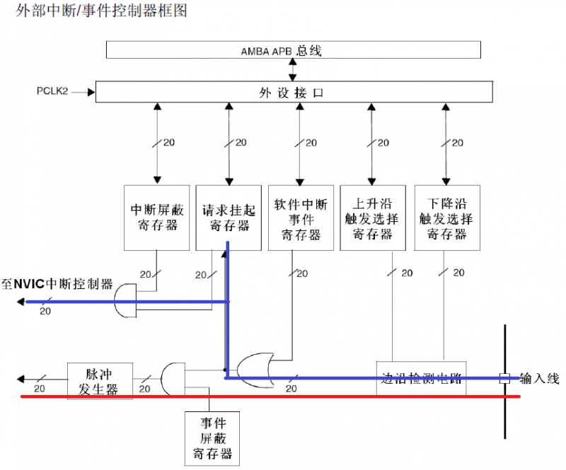
二、外部中斷/事件控制器EXTI
互聯網型產品有20個EXTI,其他的有19個,與IO口引腳相連的有16個(EXTI0-EXTI15),還有PVD(EXTI線16),RTCAlarm(EXTI線17),USB喚醒(EXTI線18),以及互聯網型的ETH_WKUP(EXTI線19)。EXTI0~EXTI15可以被映射到GPIOA-GPIOG的引腳上。
EXTI結構框圖
三、外部中斷配置
配置外部中斷使用STM32外設庫函數,涉及"stm32f10x_exti.h"、"stm32f10x_exti.c"、"stm32f10x_gpio.h"和"stm32f10x_gpio.c"四個文件。
在本程序中將開發板上的四個按鍵均配置為外部中斷源,分別是GPIOA_0對應EXTI_Line0,GPIOE_2、GPIOE_3、和GPIOE_4分別對應EXTI_2、EXTI_3和EXTI_4。
1、使能IO口時鐘,配置IO口為輸入模式
2、開啟AFIO時鐘
RCC_APB2PeriphClockCmd( RCC_APB2Periph_AFIO, ENABLE );
3、設置IO口與中斷線的映射關系
使用GPIO_EXTILineConfig函數("stm32f10x_gpio.h"和"stm32f10x_gpio.c")該函數原型為:void GPIO_EXTILineConfig( uint8_t GPIO_PortSource, uint8_t GPIO_PinSource);
其中GPIO_PortSource取值如下:
#define GPIO_PortSourceGPIOA ((uint8_t)0x00)
#define GPIO_PortSourceGPIOB ((uint8_t)0x01)
#define GPIO_PortSourceGPIOC ((uint8_t)0x02)
#define GPIO_PortSourceGPIOD ((uint8_t)0x03)
#define GPIO_PortSourceGPIOE ((uint8_t)0x04)
#define GPIO_PortSourceGPIOF ((uint8_t)0x05)
#define GPIO_PortSourceGPIOG ((uint8_t)0x06)
GPIO_PinSource取值如下:
#define GPIO_PinSource0 ((uint8_t)0x00)
#define GPIO_PinSource1 ((uint8_t)0x01)
#define GPIO_PinSource2 ((uint8_t)0x02)
#define GPIO_PinSource3 ((uint8_t)0x03)
#define GPIO_PinSource4 ((uint8_t)0x04)
#define GPIO_PinSource5 ((uint8_t)0x05)
#define GPIO_PinSource6 ((uint8_t)0x06)
#define GPIO_PinSource7 ((uint8_t)0x07)
#define GPIO_PinSource8 ((uint8_t)0x08)
#define GPIO_PinSource9 ((uint8_t)0x09)
#define GPIO_PinSource10 ((uint8_t)0x0A)
#define GPIO_PinSource11 ((uint8_t)0x0B)
#define GPIO_PinSource12 ((uint8_t)0x0C)
#define GPIO_PinSource13 ((uint8_t)0x0D)
#define GPIO_PinSource14 ((uint8_t)0x0E)
#define GPIO_PinSource15 ((uint8_t)0x0F)
這里四個按鍵對應中斷線映射:
GPIO_EXTILineConfig(GPIO_PortSourceGPIOA, GPIO_PinSource0 );
GPIO_EXTILineConfig(GPIO_PortSourceGPIOE, GPIO_PinSource2 );
GPIO_EXTILineConfig(GPIO_PortSourceGPIOE, GPIO_PinSource3 );
GPIO_EXTILineConfig(GPIO_PortSourceGPIOE, GPIO_PinSource4 );
4、配置中斷分組(NVIC),使能中斷
voidNVIC_PriorityGroupConfig(uint32_t NVIC_PriorityGroup);
voidNVIC_Init(NVIC_InitTypeDef* NVIC_InitStruct);
這里如下調用:
NVIC_PriorityGroupConfig(NVIC_PriorityGroup_2);
//對GPIO_0,映射到EXTI0
NVIC_InitTypeDef NVIC_Struct;
NVIC_Stuct.NVIC_IRQChannel = EXTI0_IRQn;
NVIC_Stuct.NVIC_IRQChannelPreemptionPriority = 2;
NVIC_Stuct.NVIC_IRQChannelSubPriority = 3;
NVIC_Stuct.NVIC_IRQChannelCmd = ENABLE;
NVIC_Init( &NVIC_Struct );
5、初始化EXTI,選擇觸發方式
調用EXTI庫函數EXTI_Init實現,該函數原型為:
voidEXTI_Init(EXTI_InitTypeDef* EXTI_InitStruct);
在"stm32f10x_exti.h"文件中定義了以下結構體和宏:
typedef struct
{
uint32_t EXTI_Line; /*指定要使能或失能的中斷或事件線*/
EXTIMode_TypeDef EXTI_Mode; /*指定中斷線的模式*/
EXTITrigger_TypeDef EXTI_Trigger; /*設置觸發方式*/
FunctionalState EXTI_LineCmd; /*使能或失能 ENABLE or DISABLE */
}EXTI_InitTypeDef;
#define EXTI_Line0 ((uint32_t)0x00001) /* External interrupt line 0 */
#define EXTI_Line1 ((uint32_t)0x00002) /* External interrupt line 1 */
#define EXTI_Line2 ((uint32_t)0x00004) /* External interrupt line 2 */
#define EXTI_Line3 ((uint32_t)0x00008) /* External interrupt line 3 */
#define EXTI_Line4 ((uint32_t)0x00010) /* External interrupt line 4 */
#define EXTI_Line5 ((uint32_t)0x00020) /* External interrupt line 5 */
#define EXTI_Line6 ((uint32_t)0x00040) /* External interrupt line 6 */
#define EXTI_Line7 ((uint32_t)0x00080) /* External interrupt line 7 */
#define EXTI_Line8 ((uint32_t)0x00100) /* External interrupt line 8 */
#define EXTI_Line9 ((uint32_t)0x00200) /* External interrupt line 9 */
#define EXTI_Line10 ((uint32_t)0x00400) /* External interrupt line 10 */
#define EXTI_Line11 ((uint32_t)0x00800) /* External interrupt line 11 */
#define EXTI_Line12 ((uint32_t)0x01000) /* External interrupt line 12 */
#define EXTI_Line13 ((uint32_t)0x02000) /* External interrupt line 13 */
#define EXTI_Line14 ((uint32_t)0x04000) /* External interrupt line 14 */
#define EXTI_Line15 ((uint32_t)0x08000) /* External interrupt line 15 */
#define EXTI_Line16 ((uint32_t)0x10000) /* External interrupt line 16 Connected to the PVD Output */
#define EXTI_Line17 ((uint32_t)0x20000) /* External interrupt line 17 Connected to the RTC
Alarm event */
#define EXTI_Line18 ((uint32_t)0x40000) /* External interrupt line 18 Connected to the
USB Device/USB OTG FS Wakeup from suspend event */
#define EXTI_Line19 ((uint32_t)0x80000) /* External interrupt line 19 Connected to the
Ethernet Wakeup event */
typedef enum
{
EXTI_Mode_Interrupt = 0x00, //設置EXTI線路為中斷請求
EXTI_Mode_Event = 0x04 //設置EXTI線路為事件請求
}EXTIMode_TypeDef;
typedef enum
{
EXTI_Trigger_Rising = 0x08, //設置輸入線路上升沿為中斷請求
EXTI_Trigger_Falling = 0x0C, //設置輸入線路下降沿為中斷請求
EXTI_Trigger_Rising_Falling = 0x10 //設置輸入線路上升沿和下降沿為中斷請求
}EXTITrigger_TypeDef;
這里分別對0,2,3,4四個外部中斷進行設置:
對K_UP鍵中斷設置,根據電路連接,因為該鍵設置為下拉方式,在沒有按下時為低電平,按下時為高電平,所以應設為上升沿觸發。
EXTI_InitTypeDef EXTI_Struct;
EXTI_Struct.EXTI_Line = EXTI_Line0;
EXTI_Struct.EXTI_Mode = EXTI_Mode_Interrupt;
EXTI_Struct.EXTI_Trigger = EXTI_Trigger_Rising;
EXTI_Struct.EXTI_LineCmd = ENABLE;
EXTI_Init( &EXTI_Struct );
另外3個類似操作。
6、設置中斷處理函數
中斷服務函數有固定的函數名,在startup_stm32f10x_hd.s文件中已經定義,這里的四個中斷的函數名分別為:EXTI0_IRQHandler、EXTI2_IRQHandler、EXTI3_IRQHandler和EXTI4_IRQHandler。
void EXTI0_IRQHandler( void )
{
if( EXTI_GetITStatus( EXTI_Line0 ) ==1)
{
delay_ms(10);
if(K_UP==1)
{
Sound(262);
}
}
EXTI_ClearITPendingBit( EXTI_Line0 );
}
四、項目實現
1、本項目以使用STM32GPIO讀取按鍵實現按鍵操作為基礎(代碼下載地址)。
2、由于本項目需要用到EXTI相關庫函數,所以將"stm32f10x_exti.h"、"stm32f10x_exti.c"兩個文件分別復制到項目文件夾的"Lib/inc"和"Lib/src"子文件夾下,并將"stm32f10x_exti.c"文件加入到項目的"Lib "組中。
3、在項目文件夾下的"User"子文件夾下新建"Exti"子文件夾,在Keil5中新建"Exti.h"和"Exti.c"文件,并將"Exti.c"文件加入到項目的"User "組中,然后修改"Include Paths",添加".\User\Exti"路徑,以便項目中其他程序能夠引用"Exti.h"。
4、在"Exti.h"文件中添加相應的宏定義和函數聲明,內容如下:
#ifndef __EXTI__H
#define __EXTI__H
#include "system.h"
#include "stm32f10x_exti.h"
void KEY_EXTI_Init(void);
#endif
5、在"Exti.c"文件中實現KEY_EXTI_Init函數和四個中斷函數。
#include "exti.h"
#include "key.h"
#include "stm32f10x_rcc.h"
#include "misc.h"
#include "beep.h"
#include "systick.h"
void KEY_EXTI_Init(void)
{
NVIC_InitTypeDef NVIC_Struct;
EXTI_InitTypeDef EXTI_Struct;
//1、使能IO口時鐘,配置IO口為輸入模式
Key_Init(); //調用key.c中的初始化按鍵GPIO的函數
//2、開啟AFIO時鐘
RCC_APB2PeriphClockCmd( RCC_APB2Periph_AFIO, ENABLE );
//3、設置IO口與中斷線的映射關系
GPIO_EXTILineConfig(GPIO_PortSourceGPIOA, GPIO_PinSource0 );
GPIO_EXTILineConfig(GPIO_PortSourceGPIOE, GPIO_PinSource2 );
GPIO_EXTILineConfig(GPIO_PortSourceGPIOE, GPIO_PinSource3 );
GPIO_EXTILineConfig(GPIO_PortSourceGPIOE, GPIO_PinSource4 );
//4、配置中斷分組(NVIC),使能中斷
NVIC_PriorityGroupConfig(NVIC_PriorityGroup_2 );
NVIC_Struct.NVIC_IRQChannel = EXTI0_IRQn;
NVIC_Struct.NVIC_IRQChannelPreemptionPriority = 2;
NVIC_Struct.NVIC_IRQChannelSubPriority = 3;
NVIC_Struct.NVIC_IRQChannelCmd = ENABLE;
NVIC_Init( &NVIC_Struct );
NVIC_Struct.NVIC_IRQChannel = EXTI2_IRQn;
NVIC_Struct.NVIC_IRQChannelPreemptionPriority = 2;
NVIC_Struct.NVIC_IRQChannelSubPriority = 3;
NVIC_Struct.NVIC_IRQChannelCmd = ENABLE;
NVIC_Init( &NVIC_Struct );
NVIC_Struct.NVIC_IRQChannel = EXTI3_IRQn;
NVIC_Struct.NVIC_IRQChannelPreemptionPriority = 2;
NVIC_Struct.NVIC_IRQChannelSubPriority = 3;
NVIC_Struct.NVIC_IRQChannelCmd = ENABLE;
NVIC_Init( &NVIC_Struct );
NVIC_Struct.NVIC_IRQChannel = EXTI4_IRQn;
NVIC_Struct.NVIC_IRQChannelPreemptionPriority = 2;
NVIC_Struct.NVIC_IRQChannelSubPriority = 3;
NVIC_Struct.NVIC_IRQChannelCmd = ENABLE;
NVIC_Init( &NVIC_Struct );
//5、使能EXTI,選擇觸發方式
//K_UP設為上升沿觸發
EXTI_Struct.EXTI_Line = EXTI_Line0;
EXTI_Struct.EXTI_Mode = EXTI_Mode_Interrupt;
EXTI_Struct.EXTI_Trigger = EXTI_Trigger_Rising;
EXTI_Struct.EXTI_LineCmd = ENABLE;
EXTI_Init( &EXTI_Struct );
//K_LEFT,K_DOWN,K_RIGHT設為下降沿觸發
EXTI_Struct.EXTI_Line = EXTI_Line2|EXTI_Line3|EXTI_Line4;
EXTI_Struct.EXTI_Mode = EXTI_Mode_Interrupt;
EXTI_Struct.EXTI_Trigger = EXTI_Trigger_Rising;
EXTI_Struct.EXTI_LineCmd = ENABLE;
EXTI_Init( &EXTI_Struct );
}
void EXTI0_IRQHandler(void)
{
u8 i;
if( EXTI_GetITStatus( EXTI_Line0 ) == 1)
{
delay_ms(10);
if(K_UP==1)
{
for(i=0; i<100;i++)
Sound(262);
}
}
EXTI_ClearITPendingBit(EXTI_Line0);
}
void EXTI2_IRQHandler(void)
{
u8 i;
if( EXTI_GetITStatus( EXTI_Line2 ) == 1)
{
delay_ms(10);
if(K_LEFT==0)
{
for(i=0; i<100;i++)
Sound(294);
}
}
EXTI_ClearITPendingBit(EXTI_Line2);
}
void EXTI3_IRQHandler(void)
{
u8 i;
if( EXTI_GetITStatus( EXTI_Line3 ) == 1)
{
delay_ms(10);
if(K_DOWN==0)
{
for(i=0; i<100;i++)
Sound(330);
}
}
EXTI_ClearITPendingBit(EXTI_Line3);
}
void EXTI4_IRQHandler(void)
{
u8 i;
if( EXTI_GetITStatus( EXTI_Line4 ) == 1)
{
delay_ms(10);
if(K_RIGHT==0)
{
for(i=0; i<100;i++)
Sound(349);
}
}
EXTI_ClearITPendingBit(EXTI_Line4);
}
6、修改"main.c"文件,內容如下:
#include "SysTick.h"
#include "exti.h"
#include "beep.h"
int main()
{
SysTick_Init(72);
BEEP_Init();
KEY_EXTI_Init();
while(1)
{
}
}
7、編譯,下載到開發板
上一篇:STM32的中斷優先級和庫函數的 開、關總中斷
下一篇:STM32IAP程序和APP相互跳轉卡死問題
推薦閱讀
史海拾趣
除了熱水領域,AOS公司還積極拓展其業務范圍,涉足了水處理、空氣凈化等多個領域。公司堅持創新驅動的發展戰略,不斷投入研發資源,推出了一系列具有創新性和高性能的產品。這些產品的推出不僅豐富了AOS的產品線,也進一步提升了其在全球市場的競爭力。
進入21世紀后,電子行業競爭日益激烈,Eby Electro Inc意識到必須依靠技術創新才能保持競爭力。公司投入大量資金進行研發,成功推出了一系列具有自主知識產權的電子產品。其中,一款高效能、低功耗的集成電路芯片,因其出色的性能而受到市場的廣泛認可。這次技術創新不僅為公司帶來了可觀的收益,也為公司在行業內樹立了良好的技術形象。
在電子行業快速發展的背景下,DEI公司意識到只有不斷創新才能保持競爭力。因此,公司加大了對研發的投入,積極引進新技術和人才。通過不斷的努力,DEI公司成功推出了一系列具有自主知識產權的創新產品,涵蓋了多個領域。這些產品不僅提升了公司的競爭力,也為公司贏得了更多的市場份額。
面對不斷變化的市場需求和行業趨勢,Anachip公司始終保持著創新的精神。公司不斷加大研發投入,推出了一系列具有創新性的產品和技術。同時,公司還積極探索新的商業模式和市場機會,為未來發展奠定了堅實的基礎。通過持續創新和努力,Anachip公司有望在電子行業中取得更加輝煌的成就。
這些故事是基于一般性的行業趨勢和企業成長經歷而構建的,旨在展示一個電子行業中公司可能的發展軌跡。在實際情況下,Anachip公司的發展道路可能會有所不同,具體的故事需要依據該公司的真實歷史和業務情況來編寫。
在半導體材料領域,對純度的要求越來越高。Entegris通過不斷的技術創新,提升材料的純度,以滿足晶圓廠對材料的高要求。同時,隨著制程工藝的步驟增多,控制污染的環節也隨之增加,Entegris在微塵控制方面也面臨著巨大的挑戰。
在晶圓盒傳輸業務上,Entegris與臺灣的家登精密之間發生了一場長達數年的專利侵權訴訟。Entegris最終獲得了勝訴,家登被要求賠償超過3,000萬美元。這一勝利不僅保護了Entegris的知識產權,也進一步鞏固了其在半導體材料市場的地位。
|
市面上現在熱銷的P10_16X32LED點陣原理圖,獨家放送! 市面上現在熱銷的P10_16X32LED點陣原理圖,獨家放送!由于廠家保密不給原理圖和源程序,為了方便自己和大家手工制作,熬夜繪制的詳細原理圖,麻煩大蝦編個顯示漢字的程序給我, 不勝感激! 放圖:… 查看全部問答∨ |
無論是LED、螢光燈還是白熾燈具,我們都要了解其中的一個重要參數——功率因素(PFC),下我們來了解下什么是功率因素。1、功率因素功率因數表征著燈具輸出有功功率的能力。功率是能量的傳輸率的度量,在直流電路中它是電壓V和電流A和乘積。在交流 ...… 查看全部問答∨ |
|
我是新手剛剛開始實習,要學著用SPI協議,開發wifi。 其實代碼是別人已經寫好的,可惜我沒學過任何有關嵌入式開發的東西(之前都是學桌面應用程序開發的) 在WM系統下的,AKU是6.1的。 希望前輩們指點下wifi開發過程中的一些流程和代碼編寫的經驗 ...… 查看全部問答∨ |
|
|
傳三篇基于STM32應用的最新的博士論文 基于STM32處理器和PC主機的USB通信協議的實現.pdf (3.05 MB) 下載次數:271 2010-12-23 19:22 2009 山東大學 博士論文 基于STM32處理器和PC主機的USB通信協議的實現 ...… 查看全部問答∨ |
【設計工具】說明ISE+timing+constrain+的用法 wConstraints Guide: Quick Start Guide appendix H. wUsing Timing Constraints: Developmental System Reference Guide chapter 6. wTiming Analyzer: Timing Analyzer Reference/User Guide. wTRCE: Developmental System Refer ...… 查看全部問答∨ |
|
顯示的錯誤信息,跟不接學習板,采用硬件仿真的提示錯誤信息一樣。 為: fatal error unknown exception in driver(#E1) session aborted!… 查看全部問答∨ |
各位: 現有一個問題問一下大家,我在28335上移植了ucos2,現在想用它采集數據,但ucos的時鐘比較慢,無法使用,于是我想嘗試使用28335的另外一個定時器中斷采集數據,但是這個定時器中斷的頻率要遠高于ucos的定時 ...… 查看全部問答∨ |
|
atmel zigbee協議棧移植(zigduino開發板) 剛接觸zigbee,用的板子是zigduino開發板,MCU型號是Atmel公司的Atmega128RFA1,想移植zigbee協議棧上去,但不知道從何下手。 看了開發板的用戶手冊,支持atmel的bitCloud SDK,看了相關資料,還是一頭霧水。。。 想問問大家怎么移植bitCloud到板 ...… 查看全部問答∨ |
一般MCU或者ARM或者DSP有32個報文對象或者32個郵箱,每個報文對象或者郵箱都配置一個ID,而每一個CAN數據幀最大長度為8個字節,那么微控制器一共能傳輸32*8=256個字節的數據,如果系統中物理量很多,字節數大于256時,應該怎么處理?… 查看全部問答∨ |

設計資源 培訓 開發板 精華推薦
- 【下載】LAT1526 利用SPI的下溢實現回顯功能
- 【下載】LAT1509 STM32G0B1的FDCAN進行通信丟包和多包案例分享
- 【下載】LAT1511 運行Ux_Host_HUB_HID_MSC通過Hub連接U盤讀寫不穩定問題分析
- 【下載】LAT1466 USB x Device HID Standalone的移植
- 【下載】LAT1488 STM32 USBxDevice MSC standalone移植示例
- 【下載】LAT1482 STM32G0單線串口通信幀錯誤問題解析


 74V1G08S
- Microchip直播:單片機編程不再難, 利用MPLAB®代碼配置器(MCC)實現快速開發
- 【EEWORLD第二十三屆】2011年02月社區明星人物揭曉!
- 走近 AI 重磅新品 STM32N6,解鎖在 MCU 部署高性能、節能型邊緣 AI!答題有好禮~還有開發板等你拿!
- 有獎直播:Microchip適用于CryptoAuthentication™系列的可信任平臺
- 直播已結束--STM32全球線上峰會 | 新品STM32N6重磅發布,50+開發板等你抽!
- 【已結束】 電感應用知識分享|MPS 有獎直播
- TI有獎直播:伺服驅動器中電流和電壓測量解決方案
- 學AM335X課程,贏超值BB-Black團購資格,更有DIY大獎賽預熱中!
- 有獎評測:平頭哥RISC-V低功耗板——RVB2601


 京公網安備 11010802033920號