參考設(shè)計MAXREFDES220#幫助用戶快速搭建基于手指的心率和血氧飽和度的測量產(chǎn)品。
MAX30101和MAX32664為多種基于手指的應用提供集成的硬件和軟件方案。MAX32664的
固件提供處理數(shù)據(jù)所需的數(shù)字
信號處理功能。參考設(shè)計還包含三軸
加速度計,以補償運動偽跡。
參考設(shè)計提供MAX32630FTHR,用于評估主機系統(tǒng),便于開發(fā)。
設(shè)計文檔、固件及軟件可在設(shè)計資源標簽頁下載。用戶可購買
電路板以便評估。
Introduction
The MAXREFDES220# provides detailed design information to use Maxim Integrated devices to quickly implement end-to-end measurement of heart rate and SpO2 using reflective photo plethysmography (PPG).
The MAX30101 operates from a 1.8V power supply and a separate 5.0V power supply for the internal LED. Many device parameters are configurable by the MAX32644. The module can be shut down through software with zero standby current, allowing the power rails to remain powered at all times.
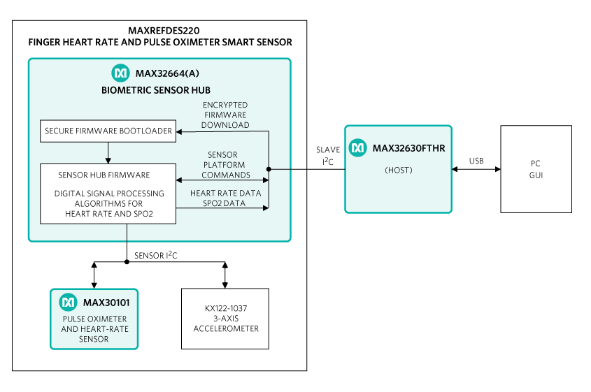
MAXREFDES220# System Board
放大+
The MAX32664 is a small, low cost, power-optimized sensor hub for finger-based pulse applications using the MAX30101. The hub collects and processes the output of the PPG and accelerometer transparently through a dedicated I2C interface. A second,standard-mode I2C interface connects to the host through a dedicated command set.
A Windows?-based GUI configures the sensors and graphically displays raw and processed heart rate and SpO2 data. It also provides the ability to collect and log sensor output for off-line evaluation.
The provided MAX32630FTHR board emulates a host system for easy development. Source code for the MAX32630FTHR firmware is freely available on the mbed site to allow customers to implement their own custom host on any platform.
As with all Maxim reference designs, the bill of materials (BOM), schematics,
layout files, Gerber files, firmware, and software are all available online.
System Diagram
Quick Start Guide
Installation Procedure
Assemble and connect the reference design hardware.
a. Remove the MAX32630FTHR and MAXREFDES220# sensor board from the package.
b. Connect the MAX32630FTHR and Smart Sensor Boards together.
c. Connect a mini-USB cable between the PC and the MAX32630FTHR.
Verify the operation of the MAX32630FTHR host
a. Immediately after connecting the USB cable, observe the LED on the MAX32630FTHR.
b. If the LED briefly turns yellow, and then blinks green, the MAX32630FTHR is programmed correctly and ready for use.
c. If the LED blinks yellow, then the MAX62630FTHR has been initialized but the sensor board is not responding. Unplug the USB cable. Separate and then reconnect the sensor board and MAX32630FTHR, and then connect the USB cable again. If the condition persists, please contact Maxim technical support for assistance.
d. If the LED turns red or blinks any other pattern or does not illuminate at all, update the MAX32630FTHR as described below.
Download and install the Maxim licensed MAX32644A firmware.
Download and install the Maxim DeviceStudio GUI software.
a. Navigate to the Maxim Integrated website, enter MAXREFDES220# into the search tool. Select the entry for MAXREFDES220# in the Product Results section.
b. On the product QuickView page, select Design Resources and download the files under “Software Files”.
c. Extract the downloaded files into any directory.
Operating the GUI
After the hardware and software installations have been completed, make sure the MAX32630FTHR is connected to the PC using the USB cable.
Launch the Maxim DeviceStudio application.
Uncheck “ADB“ under Scan Options
Press the scan button to auto-detect the Smart Sensor board that shows as PPG under "Connected Devices".
Click "Launch Tool" to run the MAXREFDES220#-specific features.
Configure the PPG settings as desired. Do not change the FIFO settings from their default values.
Select “Accelerometer Data” to display X-axis and Y-axis accelerometer results from the Sensor Board.
Select “Algorithm Data” to display the data from the IR and red LED sensors.
Updating the MAX32630FTHR firmware
These steps are only necessary if the MAX32630FTHR does not initialize as described above.
Navigate to the Maxim Integrated website, enter MAXREFDES220# into the search tool. Select the entry for MAXREFDES220# in the Product Results section.
From the product page, select Design Resources and download the files under "Firmware Files".
Extract the .bin file into any directory.
Connect one end of the ribbon cable to the black header J4 on the MAX32630FTR.
Examine the other end of the ribbon cable carefully. One side of the cable going into the black header SWD is marked by the red wire. Connect the cable and SWD header, making sure the red wire is furthest from the letters SWD.
Connect a mini USB cable between the USB connector labeled HDK and the PC.
Open a File Explorer window. The programming adapter shows as a new USB drive.
Drag and drop the downloaded .bin file onto the icon for the new USB drive. The LED begins to flash red while the MAX32630FTHR is being programmed.
When the LED stops flashing, remove the ribbon. Press the reset button on the MAX32630FTHR and verify the operation of the MAX32630FTHR.


 北京市海淀區(qū)中關(guān)村大街18號B座15層1530室
電話:(010)82350740
郵編:100190
北京市海淀區(qū)中關(guān)村大街18號B座15層1530室
電話:(010)82350740
郵編:100190
 京公網(wǎng)安備 11010802033920號
Copyright ? 2005-2025 EEWORLD.com.cn, Inc. All rights reserved
京公網(wǎng)安備 11010802033920號
Copyright ? 2005-2025 EEWORLD.com.cn, Inc. All rights reserved


 LXK3301AR001


